
 EN
EN




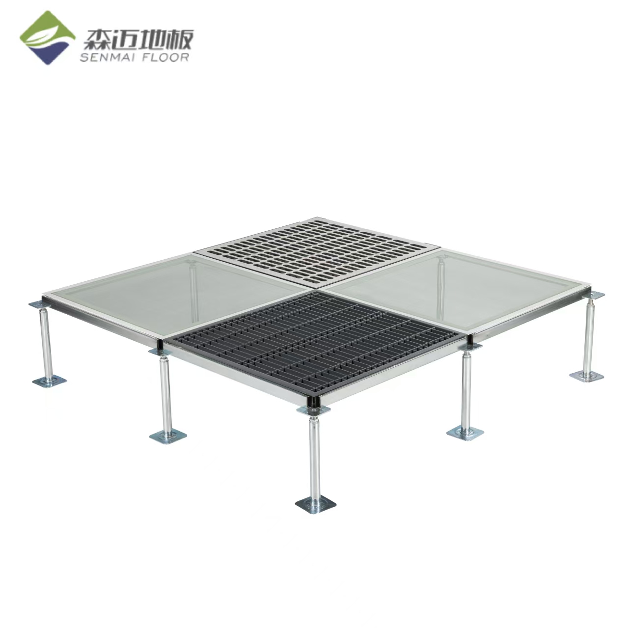
Blog Abstract: A raised access floor is only as stable as the support network beneath it. Proper pedestal installation and precise leveling prevent common post-installation defects such as rocking panels, squeaking, uneven seams, and structural sag under heavy loads. This comprehensive, step-by-step technical guide details the tools, subfloor prep, grid layout, leveling procedures, and structural reinforcement required to install a professional, heavy-duty raised access floor system.
1. Pre-Installation Preparation and Subfloor Requirements
Skipping or rushing subfloor preparation is the primary cause of floor instability. Before placing pedestals, the subfloor must be evaluated, cleaned, and marked with high precision.
Key Subfloor Steps:
-
Cleaning and Sealing: Clear all dust, concrete slurry, oils, and construction debris. Concrete subfloors should be sealed with an anti-dust coating to ensure proper adhesive bonding.
-
Laser Surveying: Use an optical transit or 360-degree rotary laser level to map the high and low points of the concrete slab.
-
Subfloor Remediation: Minor unevenness can be absorbed by the pedestal height adjustment mechanism. However, severe dips or sloped slabs require a self-leveling composite underlayment or mechanical grinding of high spots before starting installation.
2. Setting the Grid Layout
Establishing an accurate grid prevents compounded alignment errors across large room floorplates.
-
Establish the Reference Point: Determine a primary datum point (usually referenced from a structural wall or column) and project a perpendicular baseline across the room using laser lines or chalk lines.
-
Verify Squareness: Use the 3-4-5 triangle method (or a 90° cross-line laser) to ensure all grid lines intersect at exact right angles.
-
Grid Spacing: Mark grid intersections corresponding to the specific panel size—most commonly 600 × 600 mm (24 × 24 inches).
3. Pedestal Installation and Subfloor Bonding
Pedestals transfer structural loads directly from the floor panels down to the building's subfloor slab.
Fixing Methods:
-
Epoxy Adhesive Bonding: Apply a generous layer of high-strength polyurethane or epoxy resin adhesive to the underside of the pedestal baseplate before setting it on the subfloor.
-
Mechanical Anchoring: In seismic zones, cleanrooms, or high-vibration environments, secure the baseplate to the concrete slab using expansion anchors or concrete screws through pre-drilled holes in the pedestal baseplate.
Height Adjustment Mechanisms:
Access floor pedestals consist of a heavy-duty baseplate, a threaded inner rod, a locking collar nut, and an upper head plate. Standard systems offer an adjustment range of approximately ±25 mm to ±40 mm to compensate for subfloor variations.
4. Step-by-Step Leveling Procedure
Precise leveling is a systematic process that requires patience and calibrated measurement tools.
-
Set Master Reference Pedestals: Install and level four "master" pedestals at the corners of a starting module or at the highest point of the subfloor using a calibrated laser level.
-
Adjust Inner Threaded Rods: Rotate the adjustment nut to raise or lower the pedestal head until the target Finished Floor Height (FFH) is reached.
-
Bridge Grid Lines: Use a precision spirit level or laser receiver to adjust all intermediate pedestals between the master points along the grid line.
-
Lock the Mechanism: Once the correct height is verified, tighten the locking nut or engage the locking clip on the threaded collar to prevent the pedestal head from drifting or loosening due to dynamic foot traffic and rolling loads over time.
-
Slope & Angled Adjustment: On sloped concrete surfaces, use self-leveling swivel-head pedestals or angled slope-correcting shims fitted under the baseplate to keep the threaded rod perfectly vertical.
5. Installing Stringers, Panels, and Heavy-Equipment Supports
Stringer Application
For systems with a Finished Floor Height (FFH) exceeding 300 mm (12 inches), or for high-load applications, install horizontal steel stringers. Stringers tie the pedestal heads together into a rigid grid, improving lateral stability and preventing dynamic swaying.
-
Snap-On Stringers: Easily clicked into place on the pedestal head for medium-duty applications.
-
Bolt-On Stringers: Fastened with M6 steel bolts into tapped holes on the pedestal head for heavy-duty, high-load capacities.
Panel Placement
-
Lower panels directly into place from above—do not force or slide panels sideways against pedestal heads.
-
Ensure corner keyholes or alignment pins seat cleanly onto the pedestal gasket or head plate.
-
Check each panel for rocking. If a panel rocks, do not shim under the panel corners. Adjust the underlying pedestal nut until all four corners sit flat and flush.
Extra Support for Heavy Machinery
When positioning server racks, heavy transformers, or industrial machinery, supplementary support pedestals or heavy-duty structural steel bridge frames must be installed directly under the equipment footprint.
6. Common Installation Pitfalls to Avoid
| Pitfall | Cause | Consequence | Prevention / Solution |
| Panel Rocking | Uneven pedestal heads; skipping locking nuts | Loose, noisy, or unsafe floor | Fine-tune pedestal height; lock adjustment collars firmly. |
| Grid Drift | Incorrect initial chalk line layout | Cut panels at walls fail to fit; tight/binding seams | Use laser levels and verify 90° angles using the 3-4-5 rule. |
| Loose Pedestals | Bonding onto dirty, dusty, or unsealed concrete | Pedestals shift under dynamic loads, leading to floor collapse | Vacuum, clean, and prime subfloor; use recommended epoxy/anchors. |
| Lateral Instability | Omission of stringers on tall floors (> 300 mm FFH) | Floor sways or shifts laterally under heavy rolling loads | Install bolt-on horizontal stringers across all pedestal heads. |
7. Conclusion
Achieving a stable, silent, and level raised access floor relies on thorough subfloor prep, precise grid layout, and systematic leveling of every pedestal. By following these mechanical standards and utilizing quality-engineered pedestal components, facility managers and installers can ensure the raised floor system will support heavy equipment and high-traffic operations for decades without failure.